Introduction to Zone Valves for boilers
Before diving into this story, it’s worth noting that Honeywell spun off the company Resideo in 2018. As a result, zone valves labeled as either Honeywell or Resideo are technically interchangeable, ensuring compatibility for repairs and replacements.
Honeywell zone valves are a cornerstone of hydronic heating systems, playing a pivotal role in regulating heat delivery to specific zones. Widely recognized for their reliability and longevity, with a typical lifespan of 12 to 20 years, these valves have undergone significant evolution in design and functionality. This article delves into the history of Honeywell zone valves, explores the progression of their models, examines their composition, compares wiring configurations (4-wire vs. 5-wire), and offers an in-depth troubleshooting and maintenance guide.
Note that in terms of zoning, there are zone valves and zone dampers. Zone dampers are used for ductwork, typically in furnace installation and furnace repair, while zone valves are specifically designed for boilers.
History of Honeywell Zone Valves
Honeywell introduced zone valves as part of their mission to innovate and enhance heating systems. Over decades, these valves have evolved to meet changing technologies and industry demands. Early models were simple, manually operated valves, but as heating systems became more automated, Honeywell developed motorized valves with advanced features like End Switches and multiple wiring options to accommodate complex system designs.
Key Milestones:
- 1950s-60s: Introduction of basic motorized zone valves to streamline hydronic heating systems.
- 1980s: Integration of more reliable motor mechanisms and the introduction of models with replaceable components for easier maintenance.
- 2000s: Development of energy-efficient valves with improved compatibility for modern digital thermostats and smart home systems.
Different Models of Honeywell Zone Valves
Honeywell offers a range of zone valves to cater to various system configurations and demands. The most commonly used models include:
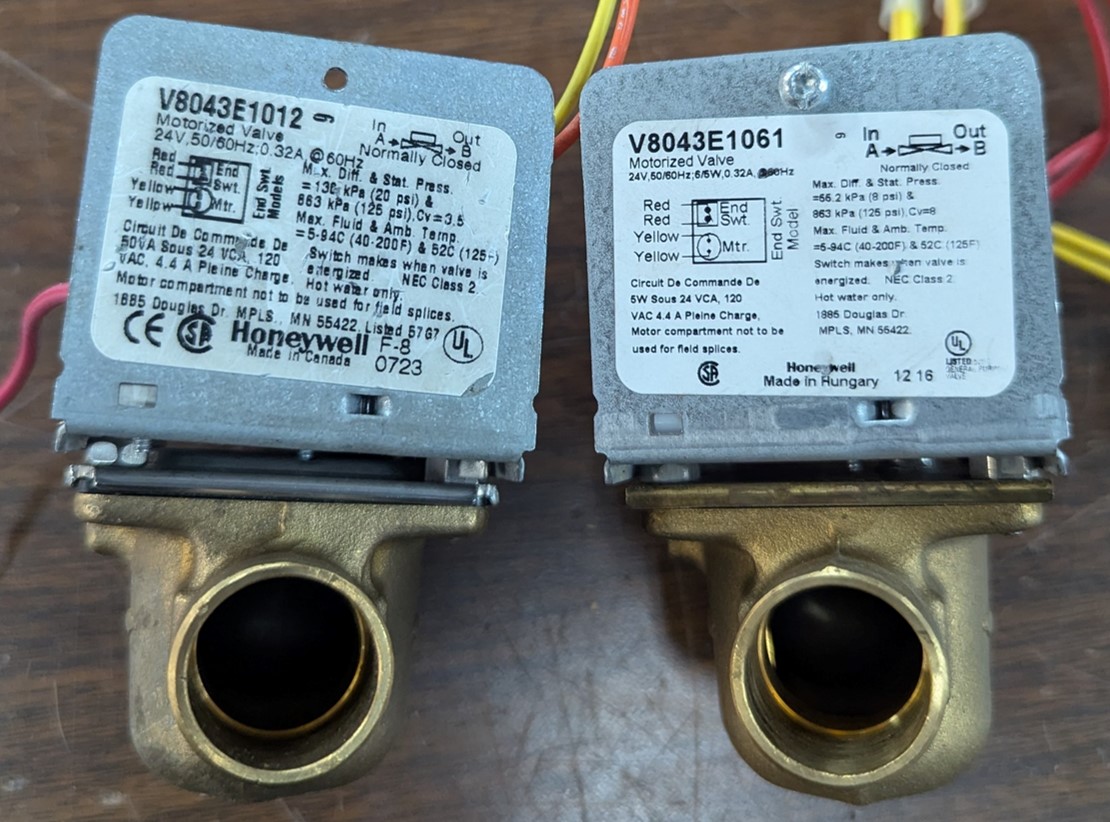
- A. V8043 Series: Designed for normally closed applications. Known for reliability and ease of maintenance.
- B. V8044 Series: Designed for normally open applications. Common in specific commercial or industrial setups.
- C. V8045 Series: Reversible models that can be configured for either normally closed or normally open applications.
- D. Motorized Zone Valves with Quick-Change Heads: Feature detachable heads for faster motor replacements.
Mostly Found in Residential V8043. Note that the water valve is normally closed while the end switch is normally open.
Wiring Configurations: 4-Wire vs. 5-Wire Zone Valves
Honeywell zone valves are available in two primary wiring configurations, 4-wire and 5-wire, each suited for specific applications.
A. 4-Wire Configuration
- Components: Two wires for the motor and two wires for the End Switch.
- Applications: Common in simpler systems where the thermostat directly controls each zone valve.
- Advantages: Simpler wiring, fewer connection points.
B. 5-Wire Configuration
- Components: Two wires for the motor, two wires for the End Switch, and an additional wire for a constant hot or common connection.
- Applications: Often used in more complex systems, such as those with smart thermostats or multiple control units.
- Advantages: Greater compatibility with advanced systems and easier integration into multi-zone setups.
Many people wonder how many zone valves a 24VAC transformer can support. The calculation is straightforward: Power = Volts × Amps. For instance, a typical 8043 zone valve draws about 0.32 amps. This means a 40VA transformer could theoretically handle up to five zone valves operating simultaneously.
Composition and Function of Honeywell Zone Valves
Honeywell zone valves are electromechanical devices designed to control the flow of hot water to designated areas in a heating system. Their key components include:
- Valve Body: A brass or durable metal housing that contains the water flow path.
- Motor: A small electric motor that operates the valve by opening or closing it.
- Gear Assembly: Transfers the motor’s motion to the valve mechanism.
- End Switch: An electrical switch that completes the circuit to the boiler, signaling it to fire and start the circulation pump when the valve is fully open.
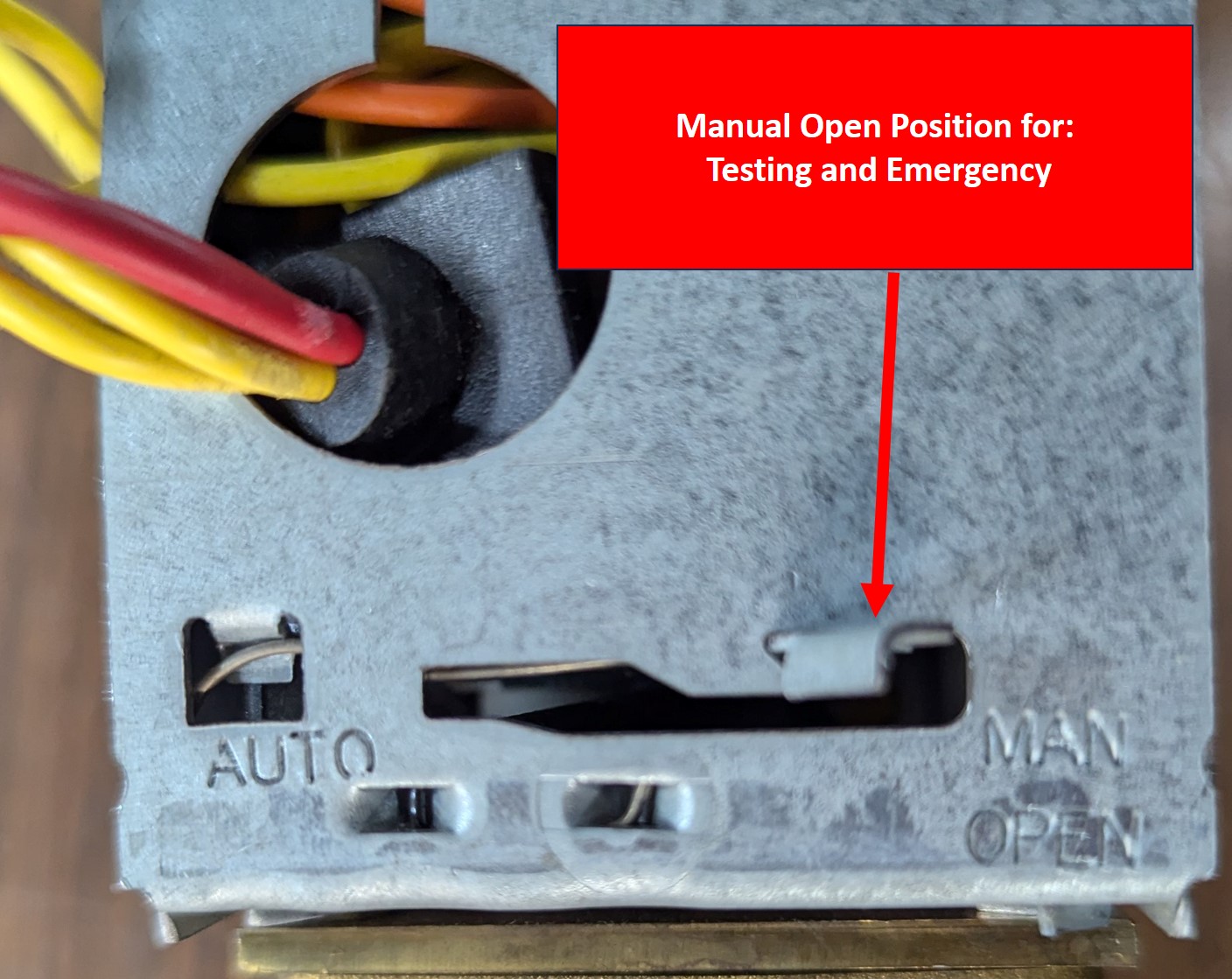
- Manual Lever: Allows manual operation in case of motor failure or during maintenance.
- Wiring Terminals: Connect the valve to the thermostat and boiler control system.